Mauer 71111 Lever Lock
Identification and Decoding Guide
By HackHouse Security Consulting
Step 0. Underlying mechanical weakness
The Mauer 71111 series lever lock exposes a measurable mechanical side channel during partial bolt interaction that allows individual lever states to be inferred without a correctly cut key.
This weakness exists due to the following properties:
- Each lever contains a distinct gate depth corresponding to a specific key cut.
- When the bolt throw is partially rotated, levers aligned with their true gate can move more freely than levers resting on serrations.
- This difference in movement is mechanically transmitted back through the lever pack by means of a dedicated lever wire tool.
- The lock provides sufficient access, via the keyway, to probe and compare lever movement individually.
By applying a uniform cut depth across all levers using a simulated key, incorrect levers bind consistently while correctly aligned levers reveal themselves through increased freedom of movement or a detectable drop.
Repeating this process for each possible cut depth isolates the correct gate position for each lever independently. This converts the original exponential keyspace into a series of linear tests, dramatically reducing the effective number of remaining combinations.
Residual uncertainty typically arises from manufacturing tolerances, wear, or ambiguous feedback between adjacent cut depths. Even then, the remaining keyspace is small enough to resolve through limited brute force testing.
Step 1. Lock identification
Visual and tactile identification
A Mauer 71111 lock can be identified through the keyway by the following characteristics:
- A distinctive central post visible in the keyhole
- An asymmetrical key profile
- Tactile lever engagement when a correct 71111 key is inserted
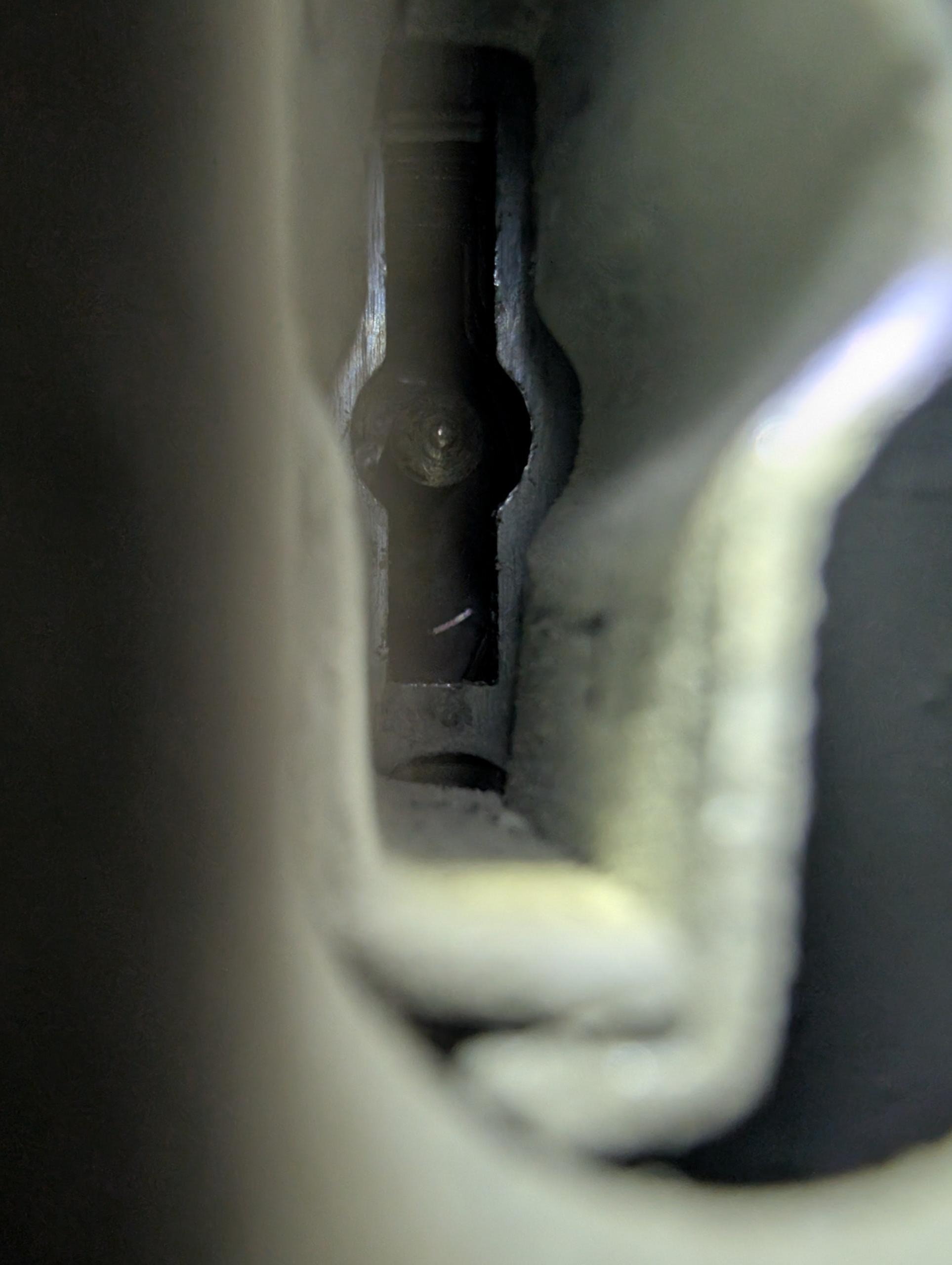
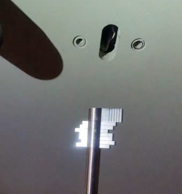
Mauer 71111 keyway showing the distinctive central post
Failure to open the lock is expected. Identification is based on correct key fit and the tactile feeling of lever engagement, not on bolt retraction.
Because one side of the 71111 key is longer than the other, the orientation of the lever pack can be determined clearly from the keyway. This allows the operator to reliably identify front to back lever order.
Having a known 71111 key available is useful for confirming both profile fit and lever engagement.
Model equivalence and naming
The following names refer to the same lock:
- Mauer 71111
- Mauer 71113
- KABA Mauer 71111
- President A
- VDS 1 Safe Lock
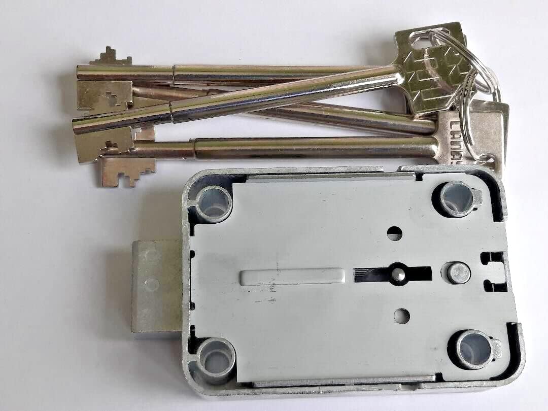
Mauer 71111 lock body and keys
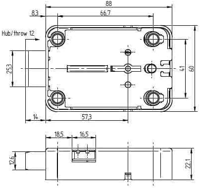
Mauer 71111 dimensions
Step 2. Decoding approach
The lock can be decoded using a dedicated lever decoding tool designed to interface with the bolt throw shaft.
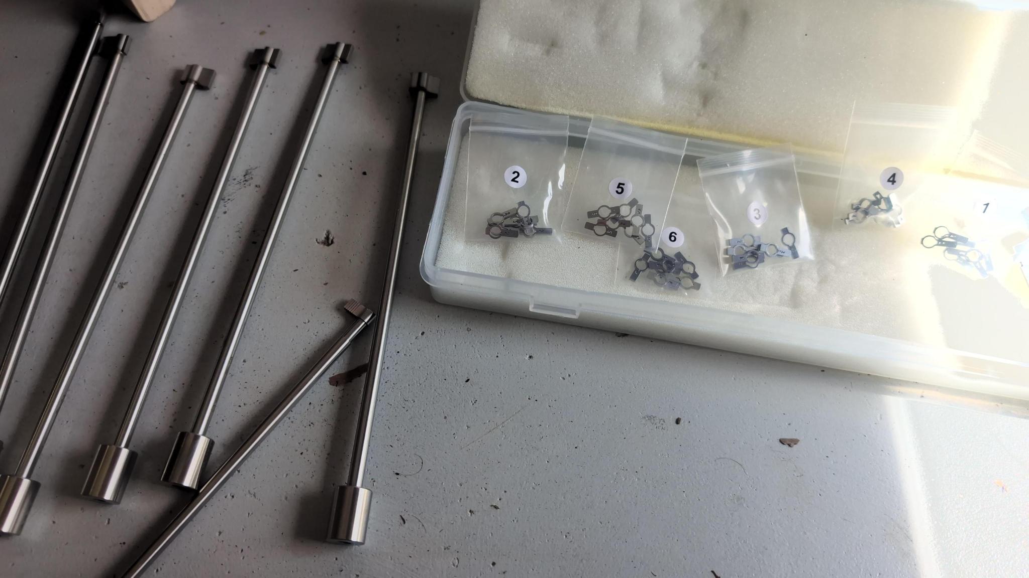
- Tool reference: MAUER President 71111 Decoder (Madelin S.A.)
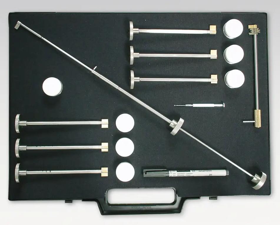
Mauer decoder toolkit
Note: Various versions of this tool exist from different manufacturers. The Madelin S.A. version is one example, but other compatible lever decoding tools designed for the Mauer 71111 series may also be available.
This tool provides graduated positioning that corresponds to individual lever locations.
Step 3. Decoding process
Tryout key and Make up key definitions
Tryout key: A tryout key is used during the decoding process. It consists of a bolt throw flag with all seven lever positions set to the same cut depth (e.g., all #1 cuts, all #2 cuts, etc.). As the Mauer 71111 lock has 6 different possible depths of cut, there are 6 included in the kit. The tryout key is inserted with the bolt throw flag, rotated 90 degrees, and then the tryout key is removed while the bolt throw flag remains in position, making room for the lever wire tool to probe the lever pack.
Make up key: A make up key is created after decoding is complete. It consists of a fixed position bolt throw flag with seven individual make up key elements corresponding to different lever cut depths (one for each lever position based on the decoded results). The make up key serves as a functional stand-in replacement for the decoded key and can be used to open the lock once the correct cut depths have been determined.
Key bitting tools and make up key parts
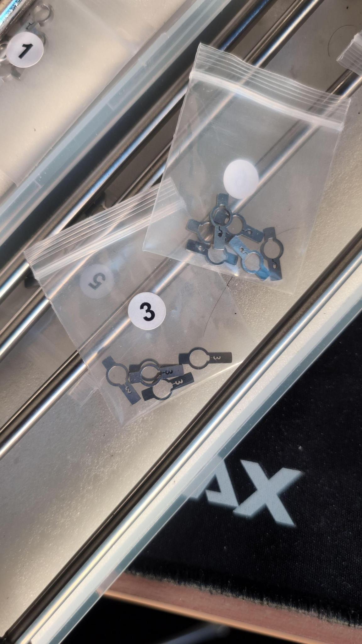
Parts used to form a make up key after decoding showing #3 and #6 cuts.
A completed make up key assembled
Initial setup and rotation logic
- Insert the bolt throw flag into the lock
- Select the first tryout key using all #1 cuts
- Insert the tryout key over the bolt throw flag shaft
- Rotate the tryout key and bolt throw flag together 90 degrees relative to the lock entry, typically clockwise
- While the bolt throw flag remains in position, rotate the tryout key only back 90 degrees, typically counter clockwise, returning it to the lock entry position
- Remove the tryout key, leaving the bolt throw flag in position
The bolt throw flag must remain rotated to hold the internal lock state in position during decoding. The removal of the tryout key makes room for the lever wire tool to probe the lever pack.
What matters is that the tryout key and bolt throw flag are moved in discrete 90 degree increments to correctly engage the lever pack.
Lever probing mechanics
- Insert the lever wire tool
Using the graduations marked on the bolt throw shaft, probe each lever position by rotating the lever wire tool left and right.
Meaningful movement is determined relative to the other levers. If most levers show little or no movement and one lever moves freely, that relative difference is the signal.
It is strongly recommended that the operator practices this technique on a cutaway lock, provided in the referenced kit or easily made at home, before attempting decoding on a live container or safe.
Lever wire tool movement consists of:
- Rotational movement to test individual levers left and right
- Lateral movement through the lever pack to feel for dips or drops
When scrubbing laterally, the operator should move in and out on both sides of the lever pack multiple times for the most accurate tactile feedback.
Levers engaged by serrations will exhibit minimal movement.
Levers aligned with a correct gate will exhibit noticeably greater freedom as they are not engaged by serrations.
Graduations and recording results
Graduations are marked on the bolt throw shaft, which the lever wire tool slides over. These graduations are pre marked and correspond to the thickness of each lever in the pack.
There is a small amount of mechanical slop between levers. This can make exact lever identification ambiguous, particularly between adjacent levers. Consistent practice prior to field use is advised.
Consistency across probes matters a lot, so if in doubt, go back and re-test it
Any probe result that potentially indicates a valid gate position should be recorded, even if uncertain. This reduces the keyspace during later brute force testing if necessary to do so.
Wear and tear of the lock meachinism over time will lead to sloppier internal mechanics which may produce false positives when decoding
Iterating through cut depths
- Once lever states for the current cut depth are recorded, remove all tools from the lock to reset all positions
- Create a new tryout key using the next cut depth (ie #2)
- Repeat the process from initial setup through recording results until you have gone through all 6 cut depths
Continue sequentially for all cut depths up to #6.
Remember! If a lever position is unclear, record it as a likely or possible value rather than discarding it. It may be a false positive or a true positive, but it is better to have it recorded than not.
After testing all cut depths, unresolved positions may remain. Ideally this should be limited to one or two positions. If more remain, re probing the lock is recommended.
Step 4. Resolving the remaining keyspace
Once the majority of lever positions are confidently identified, the remaining combinations can be brute forced using tryout keys with the remaining possible cut depth combinations.
After the correct key combination has been determined, a make up key can be assembled with the seven individual make up key elements set to the decoded cut depths. This make up key serves as a functional replacement for the correctly cut key and can be used to open the lock.
Example result
Front to back:
- Position 1 = Cut 5
- Position 2 = Cut 3
- Position 3 = Cut 4
- Position 4 = Unknown
- Position 5 = Cut 6 or 1
- Position 6 = Cut 4
- Position 7 = Cut 3 or 6
In this example:
- 4 positions are confirmed
- 2 positions have two likely values
- 1 position is completely unknown
The original keyspace of over 800,000 combinations has been reduced to:
2 x 2 x 6 = 24 possible keys
This reduction occurs because each lever is resolved independently, collapsing the exponential keyspace into a small multiplicative remainder.
The python script keyspacegen.py can be used to generate a list of possible keys for the lock. It is available here: keyspacegen.py
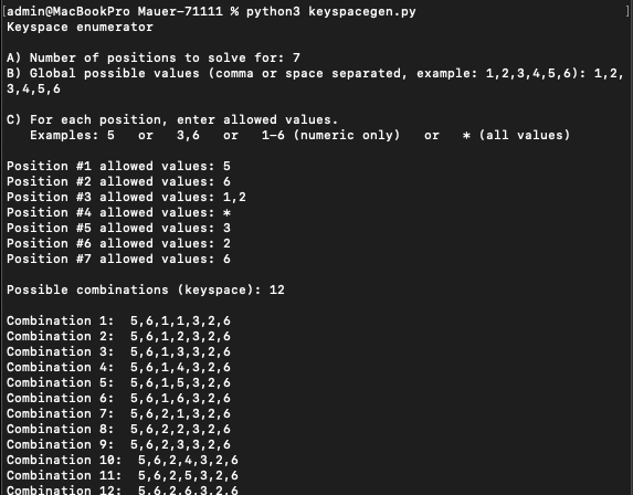
keyspacegen.py script generating possible key combinations
Physically testing all remaining combinations using a make up key typically takes approximately 30 to 60 minutes to complete (assuming you have about 24 possible keys).